Southworth Engines Corliss Engine
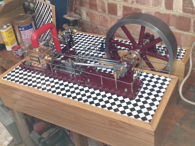
This is a big engine, 21 inches long by about 15 wide. The flywheel is 10 inches diameter.
The model was designed by Arnold Thropp and is based on several of the engines he worked with.
If you want to see a full size Corliss engine in operation, "Agnes", a 500 HP engine built by Pollit and Wigzell and originally installed at Washpit Mill, near Holmfirth, Yorkshire is now at Markham Grange Steam Museum near Doncaster and there is another one in the London Science Museum.
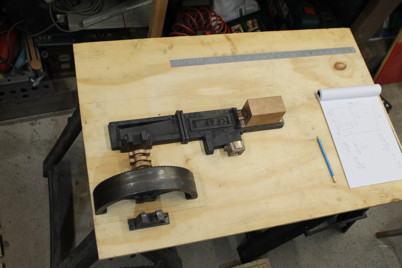
The castings laid out on the baseboard, just to get an idea of size. ( the ruler is 2 ft ).
I've now got the baseboard cut out and I've got a long piece of American oak for the sides.
Well, it's been about 4 months since I updated this page so I thought I had better put in some more words.
A lot has happened over this time - I'm amazed at how much I have actually achieved. All the parts have been made and the engine has been assembled.
Without having seen a working model, I was a bit puzzled as to how the valve grear would operate. I happened to visit the Science Museum in London recently and, as you may know, the first engine you see is a massive Corliss engine. And would you believe it, it was about to be steamed. Well, that put everything into perspective. It was a real treat to see the valves snapping shut.
So I came home and set about adjusting the valve gear. As the basic timing is set by the steam and exhaust eccentrics being fixed relative to the dead centre, it just leaves the governor to set the steam valve closing time. I think it's about right, but I won't know for sure until I actually run it.
One thing I have learned while building this engine is that there are a few errors and discrepancies in the drawings. Beware!
OK, enough words for the time being; how about a picture?
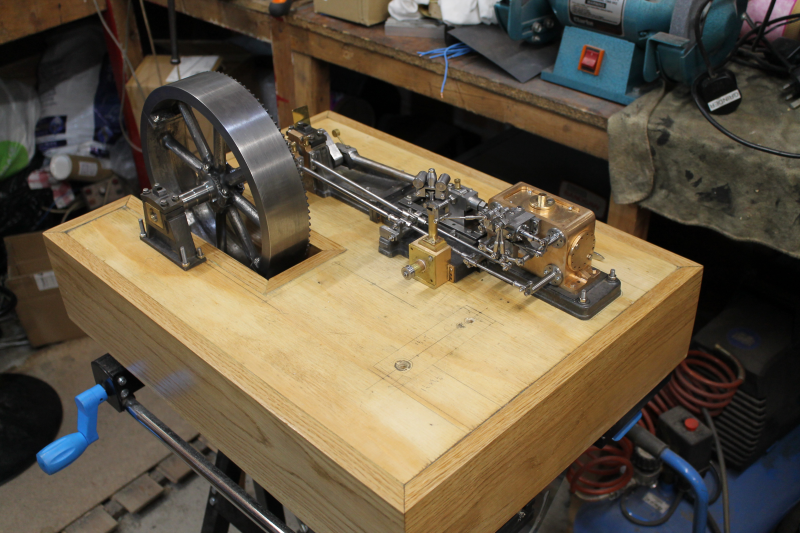
First buildup - not yet working.
Well, I've been beavering away and, after a lot of trial and tribulation, I've made some progress!
I have to say that I don't understand Mr Throp's ideas on timing.
The steam and exhaust eccentrics are keyed to the shaft, so you can't move them - without making a new shaft!- so we're stuck with that.
As designed, the eccentrics are +/- about 45 degrees either side of dead centre, which seems a bit odd to me.
The only way I could get it to run at all was to set the crank pin in line with the exhaust key.
But it DID run, even if it was a bit lumpy.
Download Video: Closed Format: "MP4"
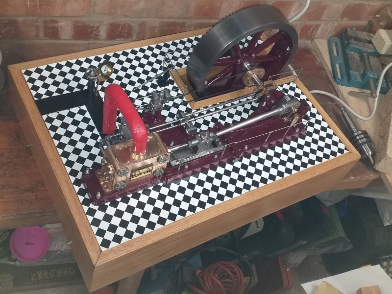
Well, it's not perfect, but it's enough encouragement to get on and finish it.I've done a bit more work - complete stripdown, paint and re-assemble and now it looks like this -
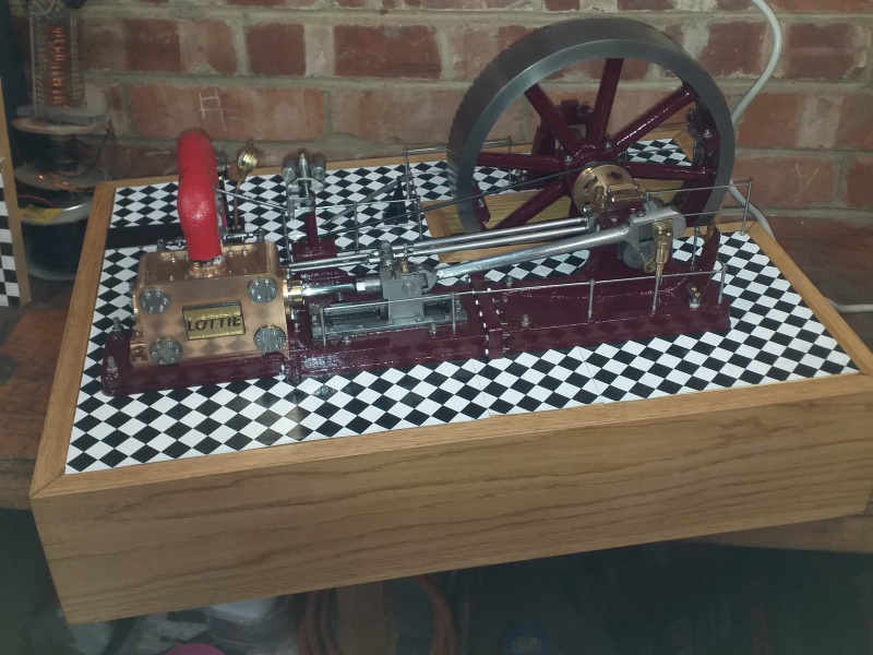
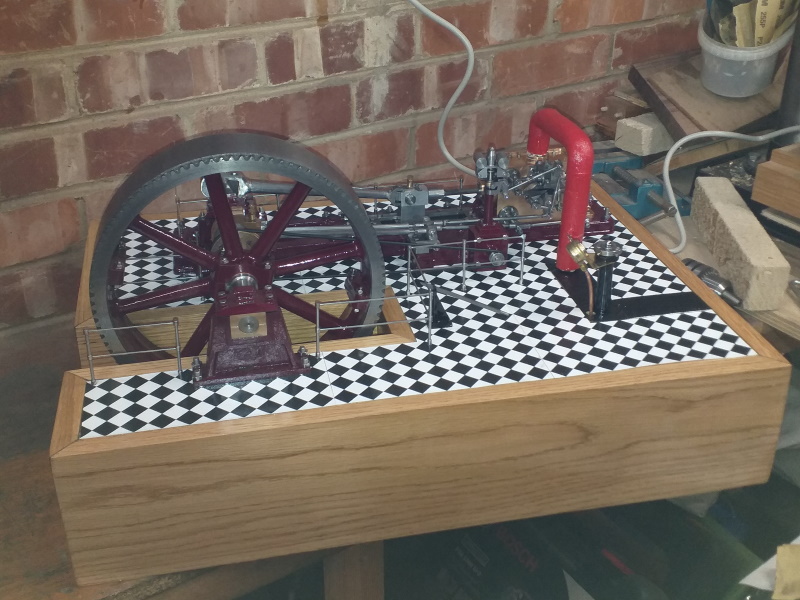
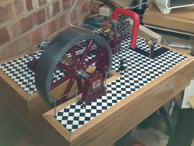
Now I reckon its finished and I'm well pleased, although it still runs like a pregnant pig!