An interesting lathe project - the Electronic Leadscrew.
This is the text of a couple of articles I had published in Model Engineer.
About a year ago, while searching the internet for something completely different, I came across the electronic leadscrew. This was something quite new to me, so I read on.
Now excuse me while I tell granny how to suck eggs! Anyone with a screw cutting lathe will tell you that in order to cut a thread, there has to be a fixed relationship between the spindle and leadscrew. If, for example, the leadscrew pitch is 2 mm and the relationship between spindle and leadscrew is 1:1, then the lathe is set up for cutting a 2 mm thread. This relationship is achieved through the use of a gear chain. If you need a different thread pitch, then you need to change the gear train. Your lathe handbook will tell you which gears to use and in what order they should be mounted. The same goes for setting up for a fine feed.
This is great, until you need to change the fine feed or cut a different thread. If you are anything like me, you won’t often use the leadscrew – far too noisy - and you will balk at the thought of changing gear wheels and setting it all up. What should be a 10 minutes job usually turns out to be at least half an hour – or more!
So, what if you could change gears at the touch of a button? Sounds pretty good to me. (Ok, bigger lathes can just about do that, but most of us don’t have professional lathes).
This is where the electronic leadscrew comes in. It uses a shaft encoder to accurately measure the spindle speed sending 4096 pulses per revolution to a small computer. The computer does all the calculations and sends pulses to a stepper motor which drives the leadscrew directly. There is also a control panel where you can select screw pitch or fine feed rate and also display various parameters. This completely replaces the gear train and a change of fine feed or screw pitch is accomplished within seconds.
OK, so now I’m hooked. Where can I get one?
Fitting one to a WM250V Lathe
First of all, we need to think about the choice of motor to drive the leadscrew. There are basically 3 types to think about – stepper motor, servo motor and hybrid stepper.
A stepper motor, on receiving a pulse from its controller, will rotate by a fixed amount. On receiving a train of pulses at a fixed rate, it will rotate at a constant speed. If it is under load, there is the possibility that it will ‘lose’ steps and not achieve the desired speed. You will only know about this when it ruins the thread you are cutting.
A servo motor will rotate at a speed determined by its control signal, using internal feedback to ensure its accuracy. A servo motor is significantly more accurate and more expensive than a stepper.
A hybrid (or closed loop) stepper uses feedback to give it almost the same accuracy as a servo but at a price lower than a servo, but more than a stepper. If it does lose steps, it sends an error signal back to the controller which could, for example, be used to stop the motor.
I chose to use a hybrid stepper.
We also have to consider how powerful the motor is (actually its stall torque) and here Clough has done us a big favour by actually testing the stall torque of various motors. It turns out that for my size of lathe a 3NM motor will work fine – as long as you don’t cut your threads in one pass!
Now, all of the electronic bits (other than the encoder, the motor and the display panel) will have to be fitted into some kind of enclosure. I found an electrical enclosure which was just the right size to fit on the end of my lathe bench; a useful place to put it – out of the way but accessible if needed. The computer board with its ‘piggy-back’ interface board, the stepper driver and the 2 power supplies are all mounted inside the enclosure. I also mounted a mains fuse and 4 multiway plugs to connect to the display, the encoder and the stepper motor. (Photos 1 & 2)
A word of warning here. The F2800 board has 2 sets of interface connectors. One of these is used for the interface board and the other is free. Make sure you get the right one and that it’s the right way round.
Don’t ask!
Thankfully, the system survived. Now for the difficult bit. Where are we going to put the display, the rotary encoder and the stepper motor?
As I said earlier, my lathe is a Warco WM250V and having seen many similar ones I’m sure they all use the same head end castings.
There are 2 usefully sized ‘holes’ through the head casting, one just the right size for the encoder and the other (which seems to have been provided primarily to hide the lathe mounting bolts) is just the right size for a stepper motor. Mounting the encoder and stepper motor into these holes, we can then use toothed belts and pulleys for the drives. I had also hoped to get rid of all the gears, but I couldn’t find a way of attaching a toothed pulley to the spindle, so I settled for using a 1:1 gearing instead, mounting the pulley on the same stub as the gear at the end of the banjo. (Photo. 3).
I made up a couple of plates from 4 mm aluminium to mount the encoder and the stepper and bolted them to the casting and I mounted the display on the side of the lathe control box. (Photos. 4 & 5).
The stepper comes with very short leads and a pair of extension cables. You can see the connectors under the lathe motor.
Now for the fun. Powering up and allowing the display to settle then turning the chuck to see speed indicated on the display. So far, so good. Turn on the lathe at a low speed. What a racket! I had hoped that getting rid of (most of) the gears would result in a quiet machine. With only one pair of gears in use it was just as noisy as a full train. I tried to adjust the spacing of the gears, but it didn’t really help.
Ok, the system works just fine – but you need ear defenders.
Time to find a Plan B. Was there another way to get rid of these gears. Looking at the 40 tooth gear, it looked to me like it could be 5 mm pitch. Now, somewhere, I’ve got a 5 mm pitch belt. Yes, it is 5 mm pitch – and of course, so is its mate. Now, if I separate those 2 gears and use them as toothed pulleys would it work? Yes it does. Now, I know I’ll have all the purists up in arms at my heresy, but that’s how we make progress! So, I ended up with a double belt drive to my encoder – still 1:1 ratio - and it works perfectly. (Photo. 6).
And the silence! Well, not perfect silence but more than acceptable. Of course, there is the possibility that the belt might run off the gears as there are no cheeks. It might also be the case that I’ll need a new belt in a couple of years. Let’s just wait and see. Anyway, all is now finished but not much to see. (Photo. 7).
Ok, time for a real trial. Chuck a bit of mild steel, about ½ inch, and turn it down a bit using fine feed. 0.5 mm / rev and cutting nicely with a 0.4 mm cut. Try 0.25 mm / rev. Quite a nice finish. Try 0.1 mm / rev. Superb finish. I’m getting to like this already. And so quiet!
Screw cutting? No problem. Imperial or metric, TPI or mm pitch, all at the press of a couple of little buttons. Magic.
As you might guess, I’m hooked, and I’m looking forward to much better finished turned parts in my projects. And I’ll probably do a lot more screwcutting.
The one thing I haven’t touched on yet is cost. The expensive bits are the hybrid stepper and controller (£86), the encoder (£25), the Launchpad computer (£46) and the bits from Clough (£73 inc. shipping and vat – but that might have gone up a bit with the recent financial hiatus). Then there are all the sundries which will bring the total cost up to about £400.
If you are considering embarking on a project like this, you need to consider the work involved. If you aren’t happy building up the electronics enclosure, then either get someone else who is competent to do it for you, or forget the whole thing. I’m assuming that as you are reading ME, then you are probably able to do the mechanical bits.
I found this a very rewarding project and once I’d got all the bits, it took around 4 weeks to complete.
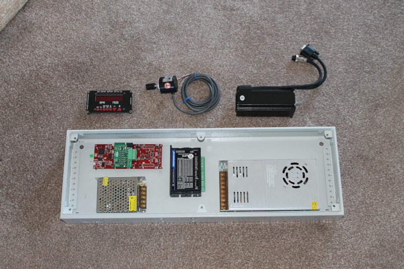
Photo. 1. The enclosure with all the bits that fit inside - and those that don’t.
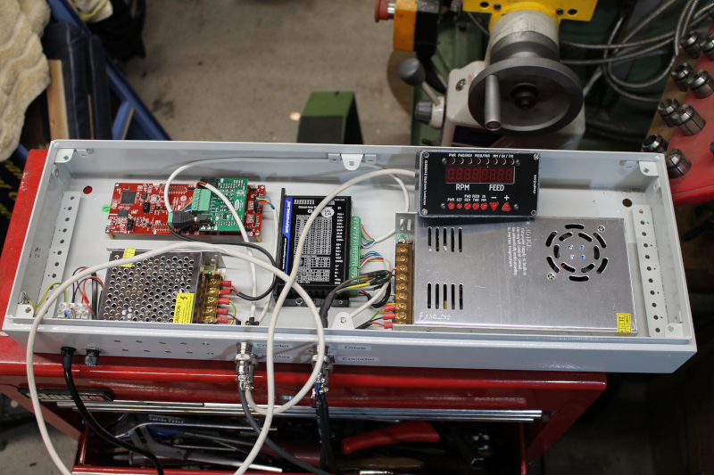
Photo. 2. The enclosure fully wired and ready to go.
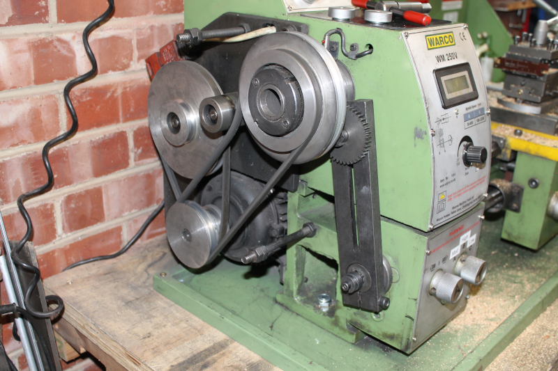
Photo. 3. 1:1 gearing using the banjo and a 40 tooth gear
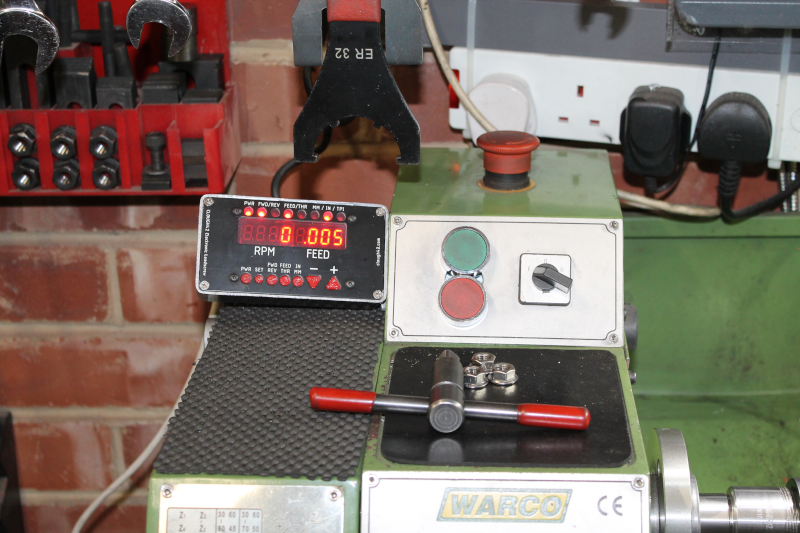
Photo. 4. The display panel mounted next to the lathe control unit.
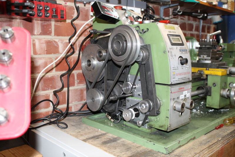
Photo. 5. The encoder and stepper mounted with their belt drives.
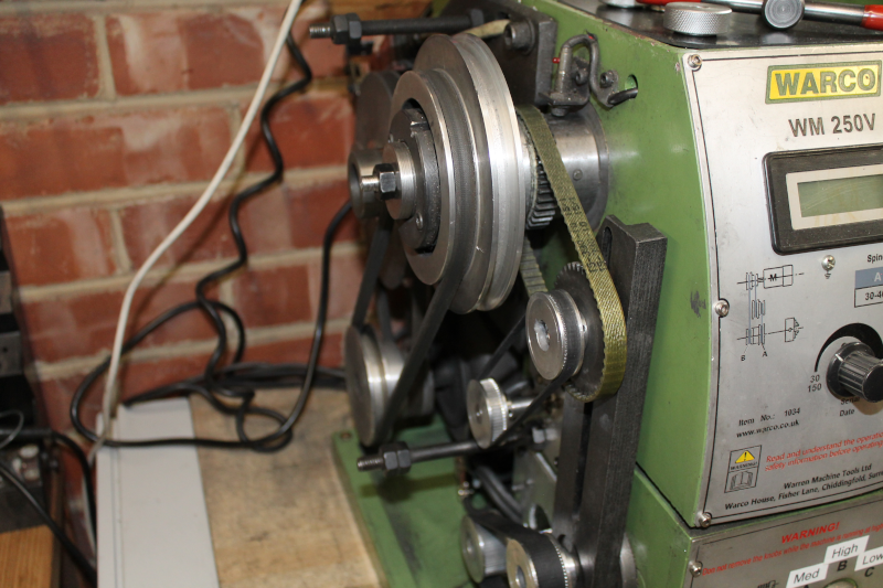
Photo. 6. The final arrangement of the encoder drive belts
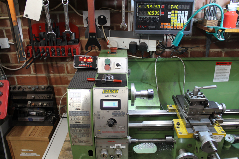
Photo. 7. Modification complete and ready to go.